Drawing guidelines for professionals
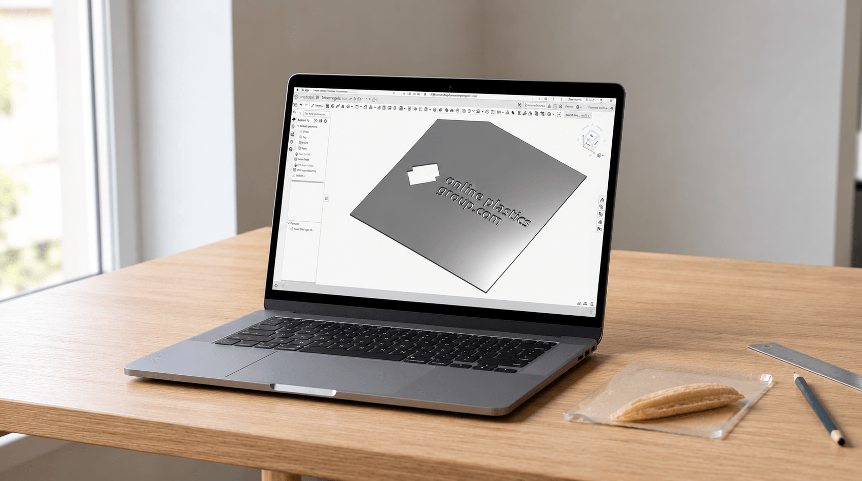
On this page, you'll find the technical specifications for DXF files from your CAD program, so we can produce your part correctly: file requirements, cutting methods, dimensional tolerance, geometry and minimum dimensions. If your file meets these requirements, upload it in the sheet calculator and order straight away.
Less experienced? Take a look at the basic drawing guidelines first.
Not working with a CAD program? With our video tutorials, you can make a DXF file in the free program Onshape.
Less experienced? Take a look at the basic drawing guidelines first.
Not working with a CAD program? With our video tutorials, you can make a DXF file in the free program Onshape.
Drawing guidelines
Your DXF file goes straight to the laser or the CNC milling machine in our own production facility in Wijster. The machine follows your drawing line by line, so the quality of your part starts with the quality of your file. The table below shows the requirements every file must meet, for laser cutting and milling.
| Specification | Requirement |
|---|---|
| File type | DXF, 2D only |
| Scale and unit | 1:1 in millimetres, also when exporting |
| Shapes per file | One shape. An outer contour with holes and cut-outs counts as one shape |
| Minimum shape | The shortest side of the outer dimensions is at least 50 mm for acrylic sheets up to and including 15 mm, and at least 100 mm for all other materials and thicker acrylic sheets |
| Maximum shape | The maximum sheet size minus 2 cm on each side. For a 2000 × 1000 mm sheet, your shape can therefore be no larger than 1960 × 960 mm |
| Distance from hole to edge and between holes | At least 2× the sheet thickness |
| Inside corners | Radius of at least 2 mm, for laser cutting and milling. This keeps pressure off the corner, so the sheet does not break. If there is no radius in your file, we add it |
| Dimensional tolerance | Approx. 0.2 mm per cut edge, up to approx. 0.4 mm over a full dimension |
| Cutting method | We laser cut acrylic sheets up to and including 15 mm, and mill all other materials and thicknesses |
Laser cutting or milling: what does this mean for your drawing?
The cutting method is fixed per material and sheet thickness. Acrylic sheets up to and including 15 mm are laser cut, all other materials and thicknesses are milled. The cutting method determines how inside corners and cut edges are finished.
Laser cutting
Laser cutting is the method we use for acrylic sheets up to and including 15 mm thick. The laser beam cuts out your DXF file line by line, without any pressure on the sheet, so your part comes out of the sheet exactly to size, with clear, smooth edges.
| Laser cutting | |
|---|---|
| Material | Acrylic sheets up to and including 15 mm |
| Cutting line | The laser cuts on the outside of the outer contour and on the inside of holes and cut-outs, with a deviation of approx. 0.2 mm per contour line |
| Load | Laser cutting is contactless. There is no mechanical load on the sheet, so the part does not deform during cutting |
| Inside corners | Radius of at least 2 mm. This prevents stress on the corner and stops the sheet from breaking. If the radius is missing from your DXF, we add it. |
| Outside corners and details | Sharp outside corners and fine details are possible. |
| Cut edge | Clear, thanks to the heat of the laser. Finishing is not necessary |
Milling
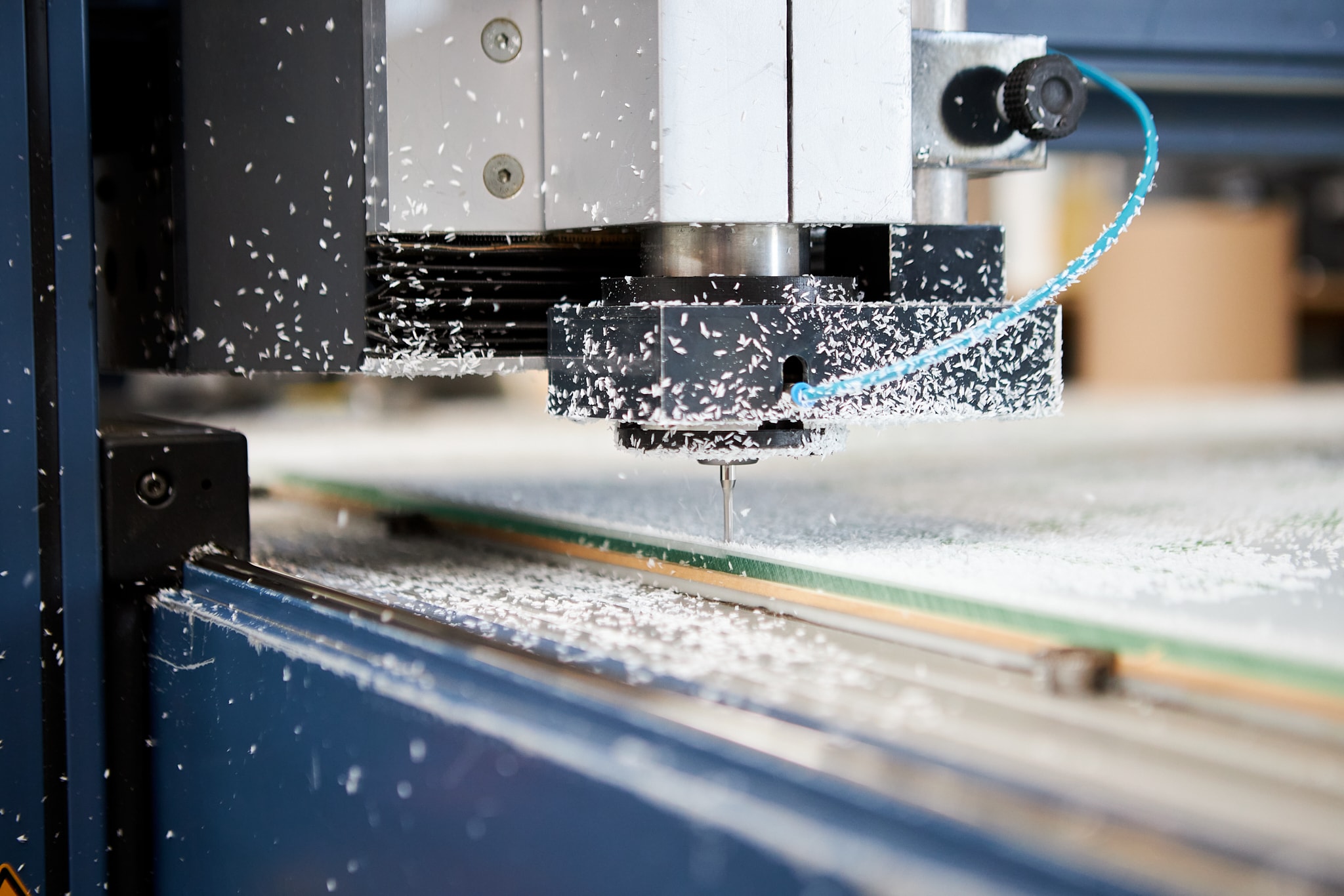
Milling is the method we use for thick and hard sheet materials. The computer controlled CNC milling machine follows your DXF file line by line, so your part comes out of the sheet exactly to size.
| Milling | |
|---|---|
| Material | Acrylic sheets thicker than 15 mm, polycarbonate, HPL, foam and solid PVC, ACP, HDPE and HMPE |
| Cutting line | The milling cutter runs along the outside of the outer contour and the inside of holes and cut-outs. This way, the part comes out at the drawn size, with a deviation of approx. 0.2 mm per cut edge. |
| Inside corners | Radius of at least 2 mm. A rotating milling cutter cannot make a sharp inside corner, and the radius prevents stress on the corner and stops the sheet from breaking. If the radius is missing from your DXF, we add it. The larger the radius, the better. If a part with sharp corners needs to fit into a cut-out, draw dogbone or T-bone cut-outs in the inside corners. These give room to the sharp corners of the part that fits in. |
| Cut edge | Matt with a white haze, a milling mark may be visible. The edges are delivered burr free. |
Dimensions and tolerances
Does your part need to fit into or connect to something? Then the tolerances below are important. They determine how much your part can deviate from your drawing, and how much clearance you need to allow yourself during installation.
Dimensional tolerance: approx. 0.2 mm per contour line, for laser cutting and milling. Over the total width or length of a part, this adds up to approx. 0.4 mm.
Draw to nominal size: draw at a scale of 1:1 in millimetres, to the nominal final size. We take care of kerf compensation ourselves. Do not draw a toolpath or kerf.
Thermal expansion: plastic expands and contracts with changes in temperature. The expansion coefficient differs per material. You'll find it on the product page of the material. Allow clearance at the edges during installation, especially for large parts and outdoor applications.
Drill holes, cut-outs and inner contours
Holes and cut-outs are the parts of a DXF file that most often need adjusting. We cannot make a hole that is too small or too close to the edge, or it makes the sheet vulnerable. Below, you can read which minimum sizes and distances apply, and which operations we do not (yet) carry out.
Minimum diameter: the smallest drill hole diameter depends on the material and sheet thickness, see the table below. This minimum size also applies to all other dimensions in your DXF file, like slot widths and narrow cut-outs.
Edge distance and centre distance: keep at least 2× the sheet thickness between a hole and the outer contour, and between two holes.
Not possible: line engraving, surface engraving, countersinking, tapping and bevelled edges are not yet possible.
| Material | Sheet thickness | Minimum drill hole | Sawing only |
|---|---|---|---|
| HPL / Trespa® | 3–10 mm | 6 mm | 12, 15 and 20 mm |
| ACP | 2, 3, 4 and 6 mm | 2 mm | – |
| Solid PVC | 2–5 mm | 6–10 mm | 2 mm | 4 mm | 12, 15 and 20 mm |
| Foam PVC | 2–5 mm | 6–10 mm | 2 mm | 4 mm | 13 and 19 mm |
| HMPE | 4–12 mm | 4 mm | 15 and 20 mm |
| HDPE | 3–5 mm | 6–12 mm | 2 mm | 4 mm | 15 and 20 mm |
| Acrylic (GS) | 2–12 mm | 15 and 20 mm | 3 mm | 4 mm | 25 and 30 mm |
| Acrylic XT | 2–10 mm | 12–20 mm | 3 mm | 4 mm | 25 and 30 mm |
| Polycarbonate | 2–10 mm | 3 mm | 12 and 15 mm |
Common errors in DXF files
These are the errors we come across most often in DXF files, with how to prevent each one. Please note: we produce based on your file. If it does not meet the drawing guidelines, we may cancel your order. If a part is not right because of an error in your file, unfortunately we cannot refund it.
Open contour: a contour is not fully closed. The part cannot be produced. Check that all entities connect to each other.
Duplicate entities: lines lie on top of each other and are cut twice, which damages the cut edge. Remove duplicate and overlapping lines.
Sharp inside corner: a sharp inside corner puts stress on the corner and cannot be made with a milling cutter. Every inside corner gets a radius of at least 2 mm, for laser cutting and milling. Take this into account for fits.
Text not converted: text that has not been converted to contours cannot be cut. Convert text to contours and check that every letter is closed.
Wrong unit: the file was drawn or exported in inches, centimetres or pixels, so the part does not come out at the right size. Always draw and export in millimetres.
Learn here how to easily make a DXF file yourself in Onshape with our video tutorials.
Learn here how to easily make a DXF file yourself in Onshape with our video tutorials.
Checklist before uploading
Go through this checklist before you upload your file. That way, you can be sure we can produce your part.
File
-
Drawn and exported at a scale of 1:1 in millimetres
-
One shape per file, 2D only
Geometry
-
All contours closed, line thickness 0.2 mm or thinner
-
No duplicate or overlapping entities
-
Splines and blocks converted to lines, arcs or polylines
-
Text converted to contours
-
No dimensions, hatching, fills or frames. Also no construction lines, title blocks or geometry on other layers that should not be cut
Dimensions
-
At least 5 × 5 cm for acrylic sheets up to and including 15 mm, at least 10 × 10 cm for all other materials and thicker acrylic sheets. No larger than the sheet size minus 2 cm all round
-
Drill holes and other small dimensions meet the minimum diameter in the table
-
Edge distance and distance between holes at least 2× the sheet thickness

Further reading
Ordering for your business, or want to go through the basics first? You'll find both here.

Ordering for businesses
Discover why businesses order from us: our own production, careful packaging and fast delivery.
Basic drawing guidelines
New to DXF files? In the basic drawing guidelines, you can read step by step which requirements your drawing needs to meet.